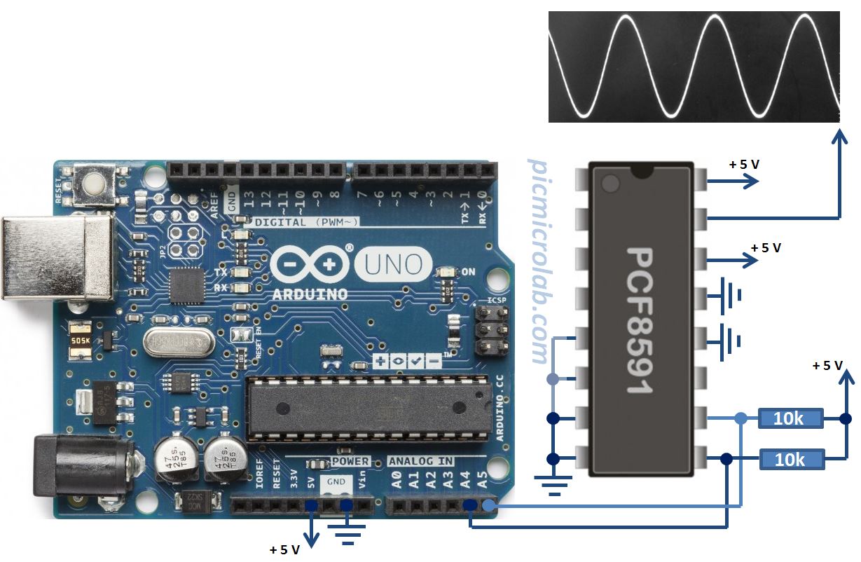

Pull-up resistors are used to keep both wires in a HIGH state by default. The SCL line carries the clock signal used for communication timing. The SDA wire is used for sending the actual data back and forth between the master and slave devices. The BusĪn I2C bus is simply two wires that connect all of the I2C devices in the network.

When sending data on the bus, only one device can send data at a time. Slave devices respond to whatever a master device sends. Master devices can send and receive data. The I2C address makes it possible for a master device to send data to a particular slave device on the bus. Slave DevicesĮach slave device has an I2C address that is used to identify the device. I2C networks can have multiple master devices and slave devices. The master and slave devices are connected by a bus. The I2C NetworkĪn I2C network consists of a master device and a slave device. It covers all of the steps, diagrams, and code you need to get started. LightMeter.BONUS: I made a quick start guide for this tutorial that you can download and go back to later if you can’t set this up right now. Uint16_t lux = lightMeter.readLightLevel() Īnother alternative is to keep the TwoWire object in a local scope so that it gets destroyed when you leave that scope - maybe with a special function for it: LightMeter.begin(BH1750::ONE_TIME_HIGH_RES_MODE,0x23,I2Clightmeter)

So instead you have to use dynamic allocation to control it: TwoWire *I2Clightmeter But you can't do that with the way you normally define the object. The ESP32 system is set up so that if the TwoWire instance is destructed the I2C bus is released. However it means changing how you define your I2C object. There is a way of doing it that's ESP32 specific.


 0 kommentar(er)
